Controlling Viparspectra Lights

Got my boards in yesterday, thanks Michael! Waiting on an SD card adapter since my old one apparently was mangled by the dog...

btw, there’s these cool little logos on the back of the new boards, thought it was a neat touch
50C55E13-8715-40FB-82A9-DE855BE2B14E.jpeg
 
Got my boards in yesterday, thanks Michael! Waiting on an SD card adapter since my old one apparently was mangled by the dog...

btw, there’s these cool little logos on the back of the new boards, thought it was a neat touch
50C55E13-8715-40FB-82A9-DE855BE2B14E.jpeg
Yeah I love the stickers also...:)
 
Got my boards in yesterday, thanks Michael! Waiting on an SD card adapter since my old one apparently was mangled by the dog...

btw, there’s these cool little logos on the back of the new boards, thought it was a neat touch
50C55E13-8715-40FB-82A9-DE855BE2B14E.jpeg
Good luck with your build! The QA stickers make sure I don't send out any untested boards, and make it a little more fun to have helpers hang out while performing QA. :)
 
Quick question here, what have you guys done with the front screen panel on the lights once set up with the new boards?

I think it would look nice having the time show up on the front panel instead of a blank space, but I'm not sure how feasible it is to power the just the clock display using the viparspectra's original board.
 
I'm in awe at how clean your boards are, what's your secret? Great job!
It takes a bit of work to get the boards clean. It was definitely a learning curve for me, and way more process than I expected.

I use RODI water and Alcojet detergent to clean the boards. Most boards get cleaned at 50 °C in an ultrasonic cleaner for 5 minutes, then a rinse in more RODI water. Sometimes I have to break out a fingernail and toothbrush too.
 
Quick question here, what have you guys done with the front screen panel on the lights once set up with the new boards?

I think it would look nice having the time show up on the front panel instead of a blank space, but I'm not sure how feasible it is to power the just the clock display using the viparspectra's original board.
I never even thought about that. My lights are hidden by canopies (plus the lights are so bright)...

I don't see any issue with powering the front panel. I think it would just be a matter of connecting 12v and GND back to the front panel. You could make a custom cable to do this. The bottom side of the viparspectra adapters have the pins labelled.

I can draw a diagram of how I would try to make the cable if you need.

That’s what I was thinking about trying tomorrow actually. I figured just jumping off the converter board to one of the channel plugs just with 12v and ground was worth a shot.

I’d love to see what you would do if you have time to draw it up! No rush, I realized the 4 core cable I wanted to use for my aviation connectors is only rated for 30v and I should probably measure voltages before using it. Although I think that should be ok to use for connecting the adapter board to the pi hat(?)
 
Last edited:
That’s what I was thinking about trying tomorrow actually. I figured just jumping off the converter board to one of the channel plugs just with 12v and ground was worth a shot.

I’d love to see what you would do if you have time to draw it up! No rush, I realized the 4 core cable I wanted to use for my aviation connectors is only rated for 30v and I should probably measure voltages before using it. Although I think that should be ok to use for connecting the adapter board to the pi hat(?)
That's basically what I would draw. You shouldn't have any problem with your cables. The voltage on these should be around 12v.
 
It takes a bit of work to get the boards clean. It was definitely a learning curve for me, and way more process than I expected.

I use RODI water and Alcojet detergent to clean the boards. Most boards get cleaned at 50 °C in an ultrasonic cleaner for 5 minutes, then a rinse in more RODI water. Sometimes I have to break out a fingernail and toothbrush too.

Cleaning them is worse than soldering because they just don't clean. I don't really do it unless its excessive and then just use a qtip which doesn't do anything for looks. Thank goodness for no clean solder. Recently I got some water soluble which is mostly clear and doesn't leave much of a mess but something odd with the way it melts. I've seen those ultrasonic cleaners and read lots of mix reviews so never pulled the trigger, now I see these maybe I'll try it one day, those clean boards really do look pro.
 
Quick minor update, wiring up the front panel for the clock display was easy. Just piggy back off of the 12v and ground from the adapter board. I just soldered onto the back side of the adapter and plugged into one of the channel plugs on the original board.

No elephants were harmed during installation.
560F4010-0F7F-4306-9F26-BA95F8E20A64.jpeg
.

C2DEA5EE-4AD7-45CA-A363-DBFDC63F40CF.jpeg
 
Last edited:
So I’ll be doing my moonlights like Tom did using that amazon board, is there a reason we can’t just jump off the 12v and ground connections on the adapter board like I did for the front clock display? It would provide the power connection without having to put another feed into the light, but I’m not an electrical engineer so I could be thinking about this wrong.
 
So I’ll be doing my moonlights like Tom did using that amazon board, is there a reason we can’t just jump off the 12v and ground connections on the adapter board like I did for the front clock display? It would provide the power connection without having to put another feed into the light, but I’m not an electrical engineer so I could be thinking about this wrong.

@Michael Lane will probably chime in, I think that would work but you might want to know what your amperage draw is going to be, not sure if there would be any issues outside of that, I doubt you are going to be running both sets of lights at the same time.

:)
 
@Michael Lane will probably chime in, I think that would work but you might want to know what your amperage draw is going to be, not sure if there would be any issues outside of that, I doubt you are going to be running both sets of lights at the same time.

:)
It sounds right in my head, but also seems too simple to work ha.

I'm wondering if the led strips will need to overlap with the main lights (at most 5 seconds), so there's not a weird blackout for a few seconds between the two that freaks out the fish. Have you watched the transition on your lights and noticed anything like that? Or is it pretty smooth
I would be reluctant to power my moon lights from the 12v line in these lights for the following reasons.
  1. The 12v lines may not be a reliable 12v. The Mars Aqua lights have the 12v line at 8v when the lights are off. I don't recall if Viparspectra lights do this too, but it would be pretty easy to verify.
  2. Drawing excess current from the 12v line may result in reduced voltage since it would be putting more demand on that rail than normal. That may result in the fans spinning at a lower speed and/or the moonlights not lighting as expected.
  3. Drawing excess current from the 12v line may damage the driver. It may not be an issue since they already run the fans, but there could be a problem if you run fans and moonlights at the same time.

It might be fine, and you could test it out by looking at how much current the fans draw and comparing that to how much current your LEDs will draw. If the LEDs are comparable or less, then you would probably be fine as long as you don't have both running at the same time. I was surprised to find that I'm using over 500 mA when I have the moonlights on 100%. I ramp them up to 100% just before the main lights go out so there isn't a temporary blackout.

I knew Michael would have a much better answer! :)
 
I would be reluctant to power my moon lights from the 12v line in these lights for the following reasons.
  1. The 12v lines may not be a reliable 12v. The Mars Aqua lights have the 12v line at 8v when the lights are off. I don't recall if Viparspectra lights do this too, but it would be pretty easy to verify.
  2. Drawing excess current from the 12v line may result in reduced voltage since it would be putting more demand on that rail than normal. That may result in the fans spinning at a lower speed and/or the moonlights not lighting as expected.
  3. Drawing excess current from the 12v line may damage the driver. It may not be an issue since they already run the fans, but there could be a problem if you run fans and moonlights at the same time.

It might be fine, and you could test it out by looking at how much current the fans draw and comparing that to how much current your LEDs will draw. If the LEDs are comparable or less, then you would probably be fine as long as you don't have both running at the same time. I was surprised to find that I'm using over 500 mA when I have the moonlights on 100%. I ramp them up to 100% just before the main lights go out so there isn't a temporary blackout.

gotcha, thanks for the explanation!
 
Here's how I think I would connect everything. The mosfet only has 3 pins, so I'm not really sure how that breakout board exposes 7 pins. If you are not daisy chaining lights, then you can ignore the connector on the right.

Your description of connections to the mosfet board seem reasonable. I didn't find a schematic for that board, so I'm not 100% sure what is connected where. I'm almost certain you are correct though.

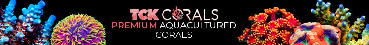
You are also correct about using a single light port on the goby hat. That's exactly how I have it in my test picture, and I'll have mine connected to the Light2 port. The following picutre also shows how I spliced into the mains voltage. Just be sure to do this with the fixture unplugged and secure and cover any mains wiring.

1589380862838.png

hey Michael, can you explain the splice on the picture above? I have some LED strips here but don’t fully understand the 120v to outlet connector part.
 
hey Michael, can you explain the splice on the picture above? I have some LED strips here but don’t fully understand the 120v to outlet connector part.

In that picture @Michael Lane is just using that splice point to feed the led strips which need 12v, if you splice 120v you will need a transformer to output 12v to the mosfet board and that is what he did. He mounted a transformer with heat shrink and used that to feed 12v to the mosfet. If you look for some of my posts you will see that instead of taping and converting 120v in the fixture I ran a separate 12v feed to the unit, either way works it just depends on how you want to do it.

Here is how I did it - https://www.reef2reef.com/threads/controlling-viparspectra-lights.698216/post-7528647

:)
 

IF YOU HAD TO TAKE A REEFING EXAM, WOULD YOU PASS?

  • Yes!

    Votes: 32 45.7%
  • Not yet, but I have one that I want to buy in mind!

    Votes: 9 12.9%
  • No.

    Votes: 26 37.1%
  • Other (please explain).

    Votes: 3 4.3%
Back
Top