DIY my own LED light with ESP8266

Fob_Reefer

Community Member
View Badges
Joined
Aug 26, 2018
Messages
85
Reaction score
14
What state or country do you live in
Massachusetts
Rating - 0%
0   0   0
I am planning of designing my own light for the 72" reef tank and was thinking of using the ESP8266 module to program and control wirelessly using Python. I haven't program much so not sure where to start. Maybe someone can point me to the right direction. I'd like to the controller to be able to set schedules with ramp-up and down, etc...

 
Awesome idea. Can you explain a bit what you already know? Without knowing much, my recommendation would be to read up adafruit articles on circuit python and esp2 based programming. Find out what type of control you need, like for metal halides you are looking at relays, while for LEDs you may be able to dim and you want the necessarity circuit (generally a simple driver like ldd etc). The complexity of the circuit and this project will highly depend upon what all you want to control, but this is certainly doable.. so far so i would say with the current state of circuit python, this is an intermediate level project and can be pulled off within a week (10-40 hours), assuming you have some familiarity with programming or electronics.
 
Yeah... I do have EE back ground years ado but haven't been doing much coding at all. I am looking to use the ESP8266 to control dimming and scheduling for the light using PWM. Maybe be doing 3-4 channels controlling various spectrum of the leds. I am looking to see if there are already coding in Python for setting schedules somewhere out there. So I don't have to re-invent the wheel (plain English is just being LAZY :))...
 
Yeah... I do have EE back ground years ado but haven't been doing much coding at all. I am looking to use the ESP8266 to control dimming and scheduling for the light using PWM. Maybe be doing 3-4 channels controlling various spectrum of the leds. I am looking to see if there are already coding in Python for setting schedules somewhere out there. So I don't have to re-invent the wheel (plain English is just being LAZY :))...

Just mod a TC-421....Has 5V PWM capability and 5 channels..and wireless.
>$40........
Granted dodgy Chinese software..

How to get 5V PWM out of it..
tcmod1.jpg
 
Great info, thanks....
now i need to learn chinese ;) ...j.k...
 
It's in English..just an odd video..
Was just kidding, thanks....
I took 2 years of chinese in high school, so should be sufficient...:D
 
Last edited:
Thought I'd post it since you didn't want to re-invent the wheel..
not sure of the 421 but the 420 has a UART port so sort of hackable.. ;)


Anyways..
https://www.tc420.net/connecting-high-power-LEDs-to-the-TC420.php
It is a great unit... now i don't even need to worry about designing the led drivers...:cool:...
Not sure if I am up to the level of hacking anything just yet...
I'll just repackage the device and slap on my own brand... Just as any big companies out there always do... :p.. and sell it for a ridiculous price..;)
 
I think the TC421 should have very sufficient current for what I need. Thanks.
Tc421 doesn't carry LED current..Above were substitutes for meanwell ldd's...

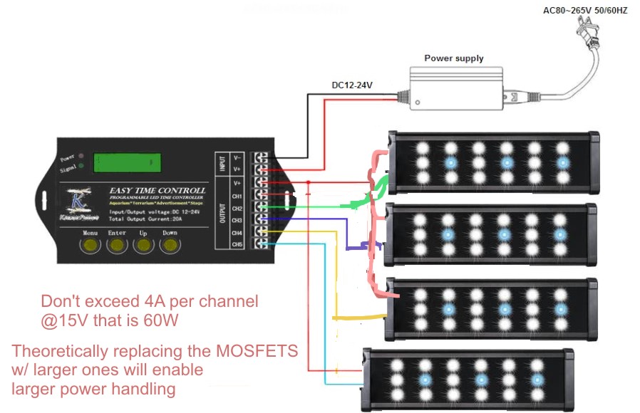
Well unless you set it up w/ constant voltage strips..and then the MOSFETS are limited to 4A (x5 = 20A) @ 12-24volts..

Btw TC420 (assume 421) can be powered as low as 9V (didn't test lower) but that is another story..
 
From the looks of the board, looks like 5 channel output have 5 mosfet to sink the current as rated for 4A@5
 
From the looks of the board, looks like 5 channel output have 5 mosfet to sink the current as rated for 4A@5
Sure but then you need to design led strings for constant voltage w/ a current control resistor. Usually not recommended for high power LEDs..
constant current is best.
simple_constant_voltage_led_strip_design.png


Meanwell PWM circuit draws VERY small amount of current. Same w/ Bluacros..

Using constant current drivers your "restrictions" are MUCH higher (theoretically 100's of Amps) since the tc-421 is only for a low level logic control (5V PWM 540Hz-ish)

You could use the same "hack" to run a larger logic NPN Mosfet though..
 
Last edited:
I think those mosfets already on the board can handle 20W each easily. From what i see on the board, i think the soic-16 is used as the led driver with pwm control from the microprocessor, that limiting/controlling the fet. The layout of that board won’t be able to handle 100W. If i can sink the heat generated, it might be able to handle it...hopefully. Or place those fets on a different board with better heat sink. Doable?
 
I think those mosfets already on the board can handle 20W each easily.
not according to my research,.. The safe operating area at 24v was 4A at DC output..
NOT the MOSFET but an example.
didn't matter because 1) not my forte and 2)wasn't going to use them
20610724319_6523e465a3_o.png

From what i see on the board, i think the soic-16 is used as the led driver with pwm control from the microprocessor, that limiting/controlling the fet. The layout of that board won’t be able to handle 100W. If i can sink the heat generated, it might be able to handle it...hopefully. Or place those fets on a different board with better heat sink. Doable?

not sure why you are making this complicated..
The 5v PWM trace to the MOSFET gate is all one needs..and a dimmable constant current driver..

What is your idea of a layout here? Maybe I'm missing something.,.
 
I think the current circuit layout is similar to this one. Using the PWMD pin, the microcontroller is controlling the input of the soic-16 and therefore, controlling the output of the FETs. So basically, the board is complete. It just that the board are tightly packed, it will burn up if all the channel max out.

Schematic-diagram-of-the-studied-LED-driver_Q320.jpg
 
Possibly.. nobody I know of that runs DIY LED's off one bothers w/ the MOSFETS..
It's switching the low side btw..if that makes any difference. Positive "ground"..

and haven't heard of one burning out yet that used just the PWM "tap" off the gate ...
micro-current draw..

Think of it as a Aduino complete w/ MOSFET switches attached..
https://www.element14.com/community...ntrolled-by-an-arduino?displayFullThread=true

Though this has been done but ??? as to longevity..
PS voltage is determined by constant voltage array specs..


mo.jpg


There is enough room to thermal glue some heats sinks to them.. if so inclined.
http://www.acvariu.ro/forum/posts/list/200/36620.page
inside-the-TC420.jpg
 
Last edited:
These FETs can handle the power easily. Just that the way it is layout right now, it will burn up the board with all channel max out, not enough heatsink...
BTW, great info on the link there :)...

Here is the link for the FETs spec.
http://www.aosmd.com/pdfs/datasheet/AOD516.pdf

I was gonna go with this design for the led driver:
article-2014february-led-color-shift-fig2.jpg
 
Do the HV version...
Eliminating using 48V ps's isn't err ..good..

like I said.. most don't bother using the MOSFET's..;)
Interesting thing though it allows you to use both strip lights and Meanwell LDD's on one channel..
Not sure on the current drain on the MOSFET ..

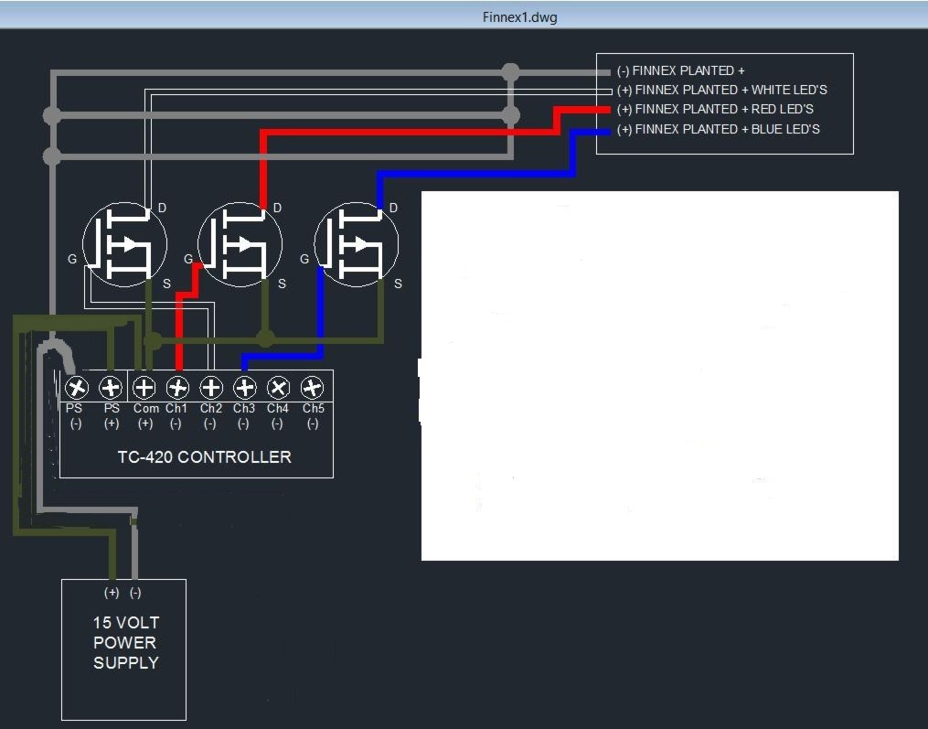
for fun.. how to split and control neg ground lights..
Output of NPN (in tc420)to gate of PNP (external)..
If you can think of a better way it would be appreciated..
psver2.jpg

pHosting.php
 
Last edited:

IF YOU HAD TO TAKE A REEFING EXAM, WOULD YOU PASS?

  • Yes!

    Votes: 32 45.7%
  • Not yet, but I have one that I want to buy in mind!

    Votes: 9 12.9%
  • No.

    Votes: 26 37.1%
  • Other (please explain).

    Votes: 3 4.3%
Back
Top