GleamRail, the successor to LEDBrick

What does it cost to do a small run of custom PCB's these days?
Shockingly cheap. If I wanted boards this size in standard thickness (1.6mm), and would be ok with no ENIG, we’re talking $5 for 10-20 of them (total), plus $40 DHL.

These were quite a bit more (20 each design plus shipping for about $220) since they’re a very thin design (0.4mm driver 0.6mm LED), high-K aluminum dielectric, and ENIG. I could spend even more and do copper boards with direct thermal pads to the LEDs. These were from PCBWay, as well as the CNCed heatsinks :)

A lot of the cost is also NRE and special runs, which is why the cheapo boards are so cheap from JLCPCB (all the batching is already built in).

Ordering 10x as many boards the price per board drops massively (10x boards for 2-3x cost), up to a point.

 
So how much for the replacement NanoBox arrays and how much would one of the Gleam arrays cost and what is the diode layout/channel wise ?
 
So how much for the replacement NanoBox arrays and how much would one of the Gleam arrays cost and what is the diode layout/channel wise ?
Nanobox? TBD. I'll break out a thread for it.

Gleamrail layout is above, but its a pretty custom setup (aka, you'll need to machine a matching heatsink). I'm not really intending for this design to go beyond a few personal builds.
 
Okay,I really am waiting on a price to see if its justifiable to replace my existing 4 arrays.

Well,it would fit on a 6"x6" makers slimsink,no ?
 
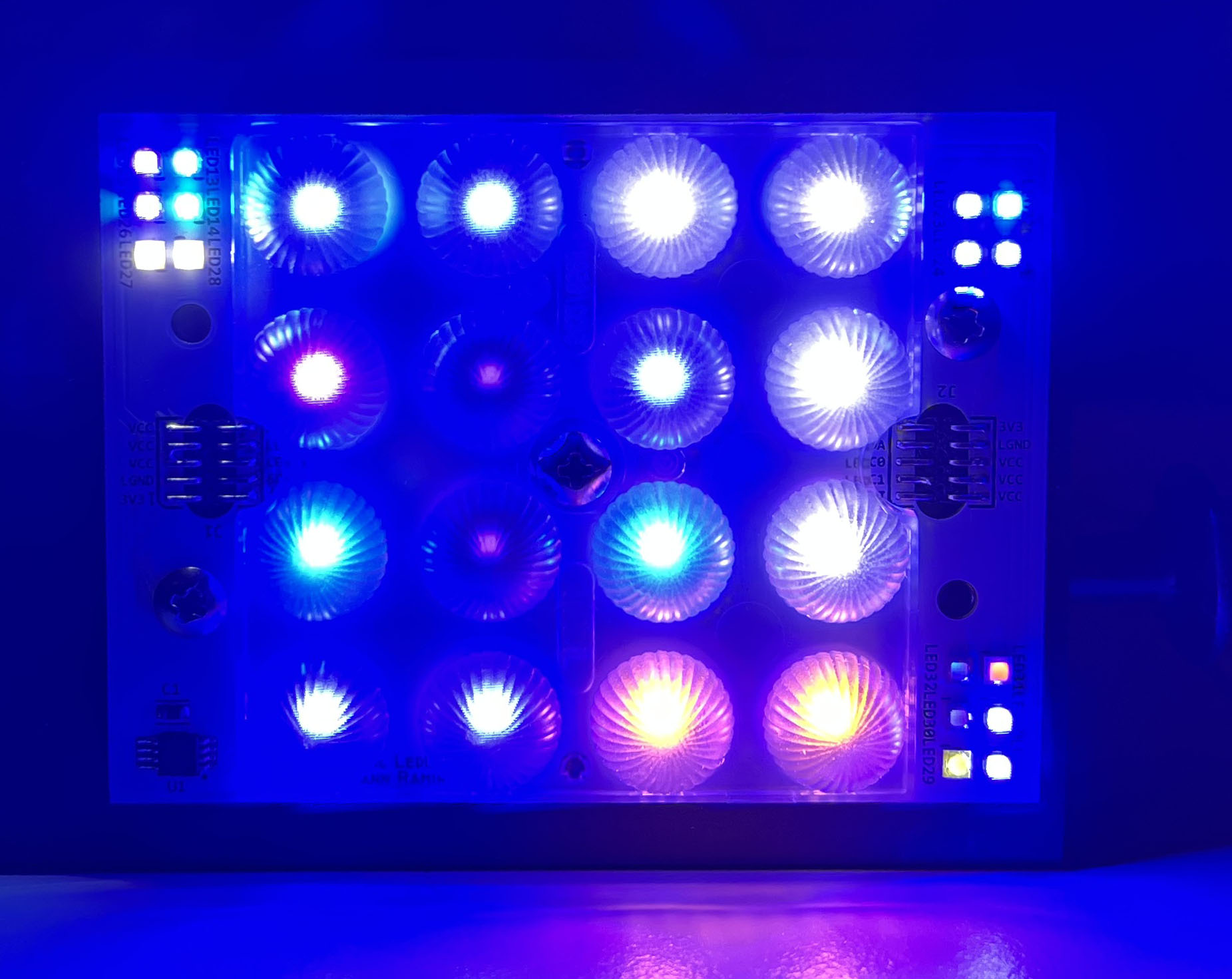
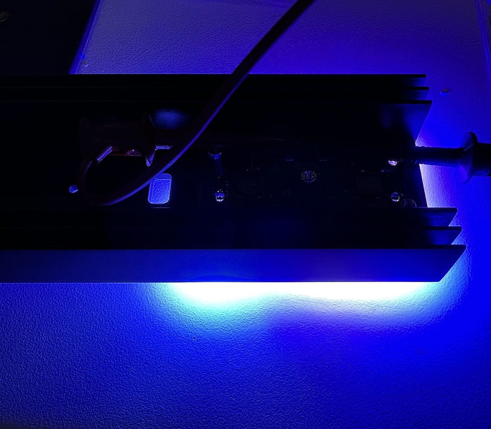
Back into GleamRail land. I built the first driver/LED pair, and had first light.

run2.jpg

run1.jpg


This runs at about 58W now with all channels at ~700mA

psu1.jpg


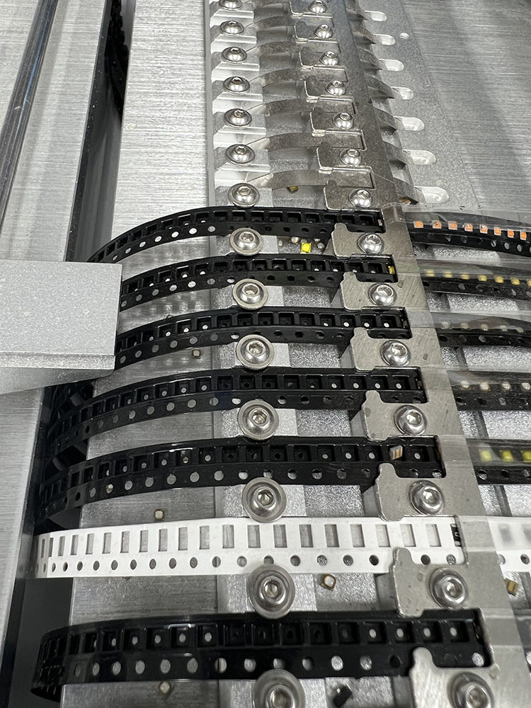
First off, the LED build. I actually used the PnP for this. I forgot how much of a general pain cheap PnPs are... you can see all the mispicks and lost LEDs :)

pnp1.jpg


Anyway, it makes a nice LED board. The connectors were added by hand later.

led1.jpg


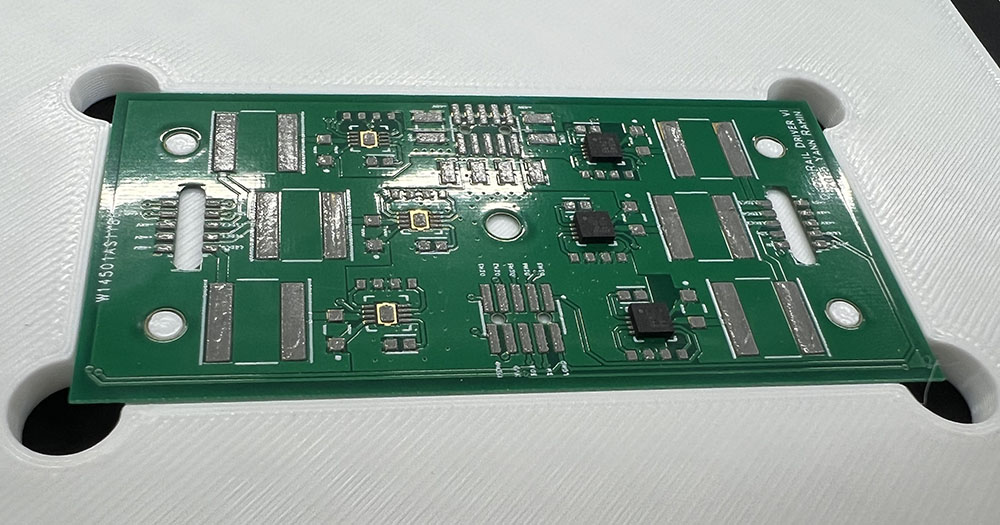
The driver was hand placed (not many unique parts). The little holder here is a 3d printed piece for aligning stencils, but also was useful holder for assembling.

driver1.jpg

driver2.jpg
 
Can these be used with just ldd's correct ? And what size is that board,I wanna say your sink measured like 2"-2.5" wide,right ?
 
2x2.7in. And yes, its just LEDs, but the headers are 0.05" (not the standard 0.1"). YMMV.

The board is laid out to assume a common anode driver (like the LM3414), so this is a weird exception case where other drivers, like LDDs, will not work.

The pinout is mirrored and allows 3 channels on each side with an on board sensor of some flavor. Note the joined VCC rail:

1678329427363.png


LED boards can be stacked in either direction (not keyed in any way), except for getting different colors on every channel.
 
Fun electronics lesson...
 

Attachments

I understood...NONE of that lol.


TLDR, you need a driver that doesn't need to connect to both sides of the LED chain. LDD needs a path from Power -> Driver -> LED + -> LED - -> Driver -> Ground, whereas the "common anode" drivers just go Power -> LED + -> LED - -> Driver -> Ground
 
Eu tenho 4 discos de leds que consomem 700mA, qual placa controladora posso usar com meus ldds? Ou melhor alguma outra forma sem ldds?
 
You may be wondering, what happened?

Well, a lot of vacation. But I'm back on it. I've been experimenting with the 3d printed case work here, and still developing what I want.

I also need to finish up the design of the dimmer/control board. Soon.
 

IF YOU HAD TO TAKE A REEFING EXAM, WOULD YOU PASS?

  • Yes!

    Votes: 32 45.7%
  • Not yet, but I have one that I want to buy in mind!

    Votes: 9 12.9%
  • No.

    Votes: 26 37.1%
  • Other (please explain).

    Votes: 3 4.3%
Back
Top