Here's some notes from when I took apart my Low Range Iron checker.
On mine the only part that actually had to be removed is opposite from the hinge side, where the white top piece is glued to the plastic body cover. Once the plastic tab is separated, the plastic body ought to come off the electronics.
(I figured out after cutting, that most of the cutting wasn't necessary)
This is a closeup of the Photocell and the attached filter.
This is a closeup of the LED.
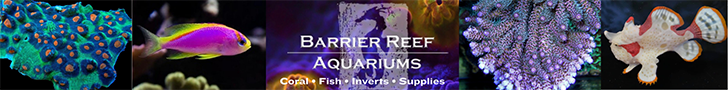
The LED is a 571-2nm yellow-green with a very narrow width. FWHM is only about ~11nm wide. The wavelength is within manufacturing tolerances of 575nm which is what it’s labeled as. I checked to see if the cyan filter was being used to shift the LED peak, but it does not shift the peak by even a nm. The filter allows all LED light through. It simply blocks anything longer wavelength than the LED itself, so any fluorescence would be blocked.
Later I realized many light sensor devices have this similar cyan filter, so it's not specific to the LED, but simply to cut off the photocell from picking up extraneous IR, or other unrelated long wavelength light. If I found the correct specs for a similar photocell, these things have a sensitivity that's throughout entire visible, and very high in IR. So I think the filter is just to tame that behavior.
(Optical Properties of the LED and filter over the photocell).
I tried and mostly succeeded to run the checker through a calibration process while measuring the current and voltage. What I found was that the calibration routine is surprisingly complex.
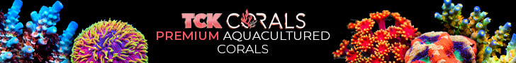
attempting to run the disassembled checker through a measurement cycle, and though it would not finish because the room light caused a “Low Light” or "Hi Light” error, it would do the “C1”-blank checking phase. Below are the Voltage and Current performance of the
LED during the “C1” check phase. It starts, then in the long calibration It will vary the light brightness every couple of seconds for about 30 seconds. Max voltage measured was ~1.9V, minimum lit voltage ~1.8. Max current was 18mA with min lit current 10mA.
(when voltage went off the chart, is where my hands slipped)
So for calibration, It shoots a series of measurements, getting the photocell response at a bunch of different LED brightness through the blank "C1" cuvette.