reef-pi :: An opensource reef tank controller based on Raspberry Pi.

Not my finest work but acceptable. Thin ABS plastic and a dremel don't always get along.

Slightly off topic but I want to incorporate a voltage/current device into the control unit and was planning on using one of these https://www.amazon.com/gp/product/B...title_srh_4?ie=UTF8&psc=1&smid=A2EFSDTWMPHWEA , however found one of these https://www.amazon.com/dp/B07D8SXQ13/ref=sspa_dk_detail_1?psc=1 which claims to interface with the raspberry-pi. Anybody have any experience with it?

IMG_20181019_170308.jpg
 
As an Amazon Associate we earn from qualifying purchases.
Ill have some spare pi-hat boards in Melbourne in the next few weeks if anyone needs one.
 
Sorry wasn't following this thread daily, but yes no problem to start a separate thread. I think the best time is when I have solved the PWM module and updated the github pages. And as stated earlier, I have a small CNC machine, but will order PCB's (PCBWAY), it takes some time but is not comparable to self drilled boards (without coating surface).
@Ranjib: I can send you an assembled and working Reef-PI_HAT it you want. Will make it easier to keep electronics and software aligned.
No rush , take your time. I don’t know you are aware , I too noticed bad pwm signal in the all in one builds , which is not present in kessil only builds. My current thought is it’s due to missing capacitors , but I didn’t get time to validate this.
I’d love to order a few hats ;-) . Let’s wait till you sort out the pwm issues and start a thread. I’ll do a build guide as well may be. I am just so stoked to see such community built things :-)
 
Not my finest work but acceptable. Thin ABS plastic and a dremel don't always get along.

Slightly off topic but I want to incorporate a voltage/current device into the control unit and was planning on using one of these https://www.amazon.com/gp/product/B...title_srh_4?ie=UTF8&psc=1&smid=A2EFSDTWMPHWEA , however found one of these https://www.amazon.com/dp/B07D8SXQ13/ref=sspa_dk_detail_1?psc=1 which claims to interface with the raspberry-pi. Anybody have any experience with it?

IMG_20181019_170308.jpg
Looking great :-)
I would love to add support for these current monitoring sensors, but I think they are not as important as the other features (like wave maker for example). These ones are also single channel (only one current source monitoring ). I am currently using a kill-a-watt to power my adjsrp8 power strip , which does something similar, except I can’t log the data, I can only see the current draw at that moment, which is kinda ok for me to get an understanding what the current draw is at that moment
 
As an Amazon Associate we earn from qualifying purchases.
Looking great :)
I would love to add support for these current monitoring sensors, but I think they are not as important as the other features (like wave maker for example). These ones are also single channel (only one current source monitoring ). I am currently using a kill-a-watt to power my adjsrp8 power strip , which does something similar, except I can’t log the data, I can only see the current draw at that moment, which is kinda ok for me to get an understanding what the current draw is at that moment
I guess what i was asking about the power monitor is how it hooks up into the pi, is it using the Dallas one wire protocol? So does it use the same input as the thermometers or would it require another circuit? Power monitoring would be nice but just knowing how much power you are using is mostly what I'm curious about.

edit: Disregard, I believe it requires an ADC. I'll keep reading up on it but in the meantime I ordered the current/voltage display unit I referenced. I can keep tabs on what the current draw is for each device by subtracting wattage off then on.
 
Last edited:
I guess what i was asking about the power monitor is how it hooks up into the pi, is it using the Dallas one wire protocol? So does it use the same input as the thermometers or would it require another circuit? Power monitoring would be nice but just knowing how much power you are using is mostly what I'm curious about.
I dont think so, from what I understand this sensor will give you analog data, which will be read to Pi using some sort of adc (analog to digital converter), like ads115, and Pi will talk to this ADC chip over i2c. Put simply we have to add some driver code for ads115 to read analog signal, and then some conversion and other code to convert the analog signal to human readable values (in amp i guess).
Does that answer your question?
 
Was on a role this morning and then neither of the buck converters are dropping voltage. I can turn the little brass screw as far as I want but 11.5 v on the output no changes. I have two from amazon both do the same.

8aece118ecc0f75dde60190122abf381.jpg
 
Was on a role this morning and then neither of the buck converters are dropping voltage. I can turn the little brass screw as far as I want but 11.5 v on the output no changes. I have two from amazon both do the same.

8aece118ecc0f75dde60190122abf381.jpg
did you try rotating them on the opposite side? I doubt the converters are bad...
 
I’m helping someone move right now but do you mean input the 12 volts on the output? One thing I am thinking about that may or may not matter is tiring the grounds together.
 
No, not that, the screw, have you tried turning clockwise and anti clockwise

Strangest thing but I think the buck converters I ordered are bad. Should be pretty simple, put 12 volts on the two “in” pins and the two out pins should be adjustable. But like I said before, it reads 11.5 volt on the out. I can turn the little brass screw all day and nothing changes regardless of the direction I turn it. Strange thing is they both do the exact same thing.
 
sensorwiring.jpg


Use some other gpio pin instead of 18 if possible (its used for pwm/light control).
Specify the GPIO pin number in the ato ui

Getting excited. Thanks for everyone and all the great posts and tech advice!

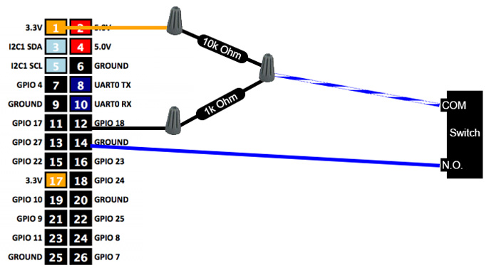
This is next tomorrow. I’m using a mechanical float switch. I have seen a couple diagrams. This one with two resistors.... I have seen one with a 10k “pull down” resistor from the GPIO input to ground and the other end of the switch to 5 volts..... and I also have heard one person using one end of the switch direct to the GPIO input and the other to 3.3v.

Which is recommended and why?
 
Getting excited. Thanks for everyone and all the great posts and tech advice!

This is next tomorrow. I’m using a mechanical float switch. I have seen a couple diagrams. This one with two resistors.... I have seen one with a 10k “pull down” resistor from the GPIO input to ground and the other end of the switch to 5 volts..... and I also have heard one person using one end of the switch direct to the GPIO input and the other to 3.3v.

Which is recommended and why?
The first one with two resistor is safest, the second one with one pull up resistor is safer and one without any resistor is least safe. All of them should work.
The resistor are there’s to protect the gpio pins from sudden reverse current or something link that. I won’t say I understand this fully, but to give an analogy with water and gating valaves, resistor acts like a safety gate . The firsts circuit protects both the power pin as well as the gpio , the second one only protects the gpio
I am sure someone with better electronics understanding will be able to explain this little bit more clearly. This same concept applies to the kessil control circuit as well , we put 1k and 10k resistor in similar fashion
 
And.... disregard. You really have to turn this thing a lot!
I knew your lm2596 modules are not bad when you shared that they are reading 11.4/11.6 V, this is very similar to my experience. They need quite a few turn, I think the amazon product page mentions the same
 

IF YOU HAD TO TAKE A REEFING EXAM, WOULD YOU PASS?

  • Yes!

    Votes: 32 45.7%
  • Not yet, but I have one that I want to buy in mind!

    Votes: 9 12.9%
  • No.

    Votes: 26 37.1%
  • Other (please explain).

    Votes: 3 4.3%
Back
Top