reef-pi :: An opensource reef tank controller based on Raspberry Pi.

Ranjib,

Definitely following along. I've been out of the hobby for a while, and I just picked up an empty 29g Biocube. I plan on reef-pi controlling everything. I'll be pulling the lights out of the hood and going w/ a dimmable 2 channel LED DIY fixture in its place, along with the expected items I'll need to be controlled (ATO, heater, can for cooling, etc). I've got a Pi3 to put towards this, so no big deal there.

Everyone:

First question:

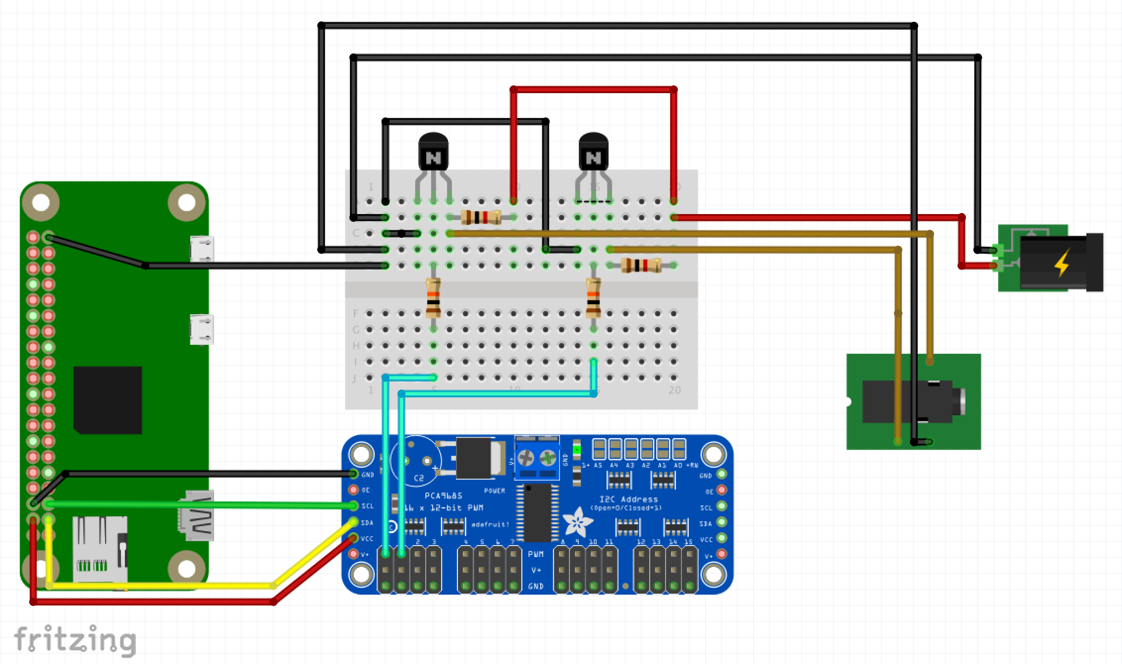
Maybe it was somewhere in the previous > 80 pages in this thread and I missed it, but does anyone have any good, clear pictures of their 10v PWM output circuit (a 2 channel setup would be even more awesome)? From where it outputs from GPIO02 and 03 on the Pi, to the PCA9685, to their resister/transistor wiring (be it on a breadboard or a DIY circuit board), to whatever their connection method to the dimmer's PWM input?

I tend to be more visual when it comes to this sort of thing (I have an art degree, so shocking, I know).

Thanks,
Andy

 
welcome back to R2R..

Thanks.

Reading through the thread I know that you're pretty much in a feature freeze leading up to the 1.0 release, but I thought I'd put in a couple of future feature requests that I'd find useful (or to put my support behind others that have already been brought up):
  • PWM fan control, based on temperature reading. I can see places this could be useful. First, for those of us with smaller tanks, it could be used with a fan to provide cooling to the tank. For my Biocube, I could see myself building a device that blows straight down into the 3rd chamber. Obviously, this would lead to greater evaporation and would need to be used in conjunction w/ an ATO. The second use would be in a light fixture. If we had a thermometer on the heatsink, we could have a turn on and ramp up point to help w/ cooling. If the heatsink is only mildly warm, why turn on the fans full blast if we don't need to?
  • Support for more probes. I understand that there's greater cost to run some of the probes, but if I could add them one at a time over a period of time, I'd be interested in several more. I'd personally be interested in salinity, pH, ORP, nitrate (I know these are CRAZY expensive and would need to come way down before I could do it).
 
Welcome Andy. For the life of me I can't find the reef-pi assigned pins table\graphic. I know it is on the github.io site somewhere. I believe it might answer your question. I will give it another shot this evening.

Cary,

I have the graphics, just something wasn't working out in my head. But as I began typing this, I think I realized where my thinking was wrong. I was looking at this image:

breadboard.png


And my brain was interpreting the output jack as only carrying one channel (i.e. I'd need a jack for each channel I wanted to control). But then I realized that the mini-jack is 3 conductor; in this case ground, PWM from pin 0 and PWM from pin 1. So, wire the input jack at the fixture end and break it out on that end to each input on the driver. I plan on using Meanwell drivers on a LDD-H-4 driver board, so that should be easy enough.

That sounds about right, right?
 
is this what you meant?

It was more the circuit in the "real world" I was having trouble visualizing. But I think I figured out where my brain was making a wrong turn. I hopefully articulated it OK a couple of posts up.

Thanks though.
 
I am jumping on-board as well. This is my very first post on the R2R. My plan is to switch from a fresh water tank to a salty one :)
I am building my inventory (a tank, pumps, lights, RO-DI, etc) and have been looking at the automation. I have the Seneye sensor and wanted to build my automation around that (it measures Ph, temperature, free ammonia, NH4, PAR, PUR, LUX). I wanted to use Rpi3 as the base for the whole thing. While researching the topic I have stumbled upon this thread. Couple of weeks back I have ordered some components and today the last of the first installment has arrived. The Rpi3 is running now the Reef-Pi with 8 relays board.
For now I want to test it in a "dry" setup and slowly build the whole "unit".
I plan to use the power sockets, temperature, ATO, doser and timers.
The software is great. It is like magic looking at the indicator LEDs to change color and the following "click" :)
Thank you Ranjib for the hours put into that. The same goes to everybody that contributed to is as well.
Here are some pictures of my trying out the Reef-Pi and the relay board with all 8 relays in "on" state.

WP_20171012_20_23_13_Rich.jpg
WP_20171012_20_23_52_Rich.jpg


WP_20171012_20_23_13_Rich.jpg
 
Sorry, but I still am not sure I know the answer to the question. Yes, sometimes I am hard-headed and thick brained (ADD actually).

I watched those videos some time ago and was convinced I could do that modification and understood it to be 0-10v. What I don't understand is the output from reef-pi. I believe it is 0-5 PWM. If that is true we need other components to make the 0-5PWM digital changed to 0-10v analog.


Again, sorry if this has been answered above, I just didn't understand the answer. Ryan, I did read you statement earlier. Are you hinting now that the mod that Mike Herman is making the exact mod that we need for reef-pi?

Ranjib, thanks for your effort on our behalf.
We are all learning these things... and we have lot of time to do so... reef keeping is a long journey :-)
reef-pi the software itself assumes pca9685 chip which generates 5v pwm. The standard build (kessil controller https://reef-pi.github.io/build-guides/lighting/) uses additional electronics to convert that to 10v pwm. I have mentioned this topic on the third bullet point, under "things to consider" section in the guide.
 
I am jumping on-board as well. This is my very first post on the R2R. My plan is to switch from a fresh water tank to a salty one :)
I am building my inventory (a tank, pumps, lights, RO-DI, etc) and have been looking at the automation. I have the Seneye sensor and wanted to build my automation around that (it measures Ph, temperature, free ammonia, NH4, PAR, PUR, LUX). I wanted to use Rpi3 as the base for the whole thing. While researching the topic I have stumbled upon this thread. Couple of weeks back I have ordered some components and today the last of the first installment has arrived. The Rpi3 is running now the Reef-Pi with 8 relays board.
For now I want to test it in a "dry" setup and slowly build the whole "unit".
I plan to use the power sockets, temperature, ATO, doser and timers.
The software is great. It is like magic looking at the indicator LEDs to change color and the following "click" :)
Thank you Ranjib for the hours put into that. The same goes to everybody that contributed to is as well.
Here are some pictures of my trying out the Reef-Pi and the relay board with all 8 relays in "on" state.

WP_20171012_20_23_13_Rich.jpg
WP_20171012_20_23_52_Rich.jpg


WP_20171012_20_23_13_Rich.jpg
I can not explain how much joy i get looking at these DIY builds :-)
The first time that LED blinks, it feels magical. First time I experienced it (and i was already 10+ years old software engineer), i was equally fascinated.. welcome to the world of physical computing
 
Ranjib,

Definitely following along. I've been out of the hobby for a while, and I just picked up an empty 29g Biocube. I plan on reef-pi controlling everything. I'll be pulling the lights out of the hood and going w/ a dimmable 2 channel LED DIY fixture in its place, along with the expected items I'll need to be controlled (ATO, heater, can for cooling, etc). I've got a Pi3 to put towards this, so no big deal there.

Everyone:

First question:

Maybe it was somewhere in the previous > 80 pages in this thread and I missed it, but does anyone have any good, clear pictures of their 10v PWM output circuit (a 2 channel setup would be even more awesome)? From where it outputs from GPIO02 and 03 on the Pi, to the PCA9685, to their resister/transistor wiring (be it on a breadboard or a DIY circuit board), to whatever their connection method to the dimmer's PWM input?

I tend to be more visual when it comes to this sort of thing (I have an art degree, so shocking, I know).

Thanks,
Andy
Welcome to r2r , and thank you for considering reef-pi :-)
Check this out: https://reef-pi.github.io/build-guides/lighting/
 
Cary,

I have the graphics, just something wasn't working out in my head. But as I began typing this, I think I realized where my thinking was wrong. I was looking at this image:

breadboard.png


And my brain was interpreting the output jack as only carrying one channel (i.e. I'd need a jack for each channel I wanted to control). But then I realized that the mini-jack is 3 conductor; in this case ground, PWM from pin 0 and PWM from pin 1. So, wire the input jack at the fixture end and break it out on that end to each input on the driver. I plan on using Meanwell drivers on a LDD-H-4 driver board, so that should be easy enough.

That sounds about right, right?
Yeah, you got it!
 
As an Amazon Associate we earn from qualifying purchases.
Ranjib - there are some typos on the Troubleshooting page in the command line part. Can I fix those? If yes - can you point me to a place where I can find out how :)
Yeah, you can fork the website repo https://github.com/reef-pi/website , and edit it online, and then submit the changes as `pull request`. All you need is a github account. I would highly appreciate that help
If thats too much, just mail me or share the typos here, and I can fix them as well.. both works
 
Thanks.

Reading through the thread I know that you're pretty much in a feature freeze leading up to the 1.0 release, but I thought I'd put in a couple of future feature requests that I'd find useful (or to put my support behind others that have already been brought up):
  • PWM fan control, based on temperature reading. I can see places this could be useful. First, for those of us with smaller tanks, it could be used with a fan to provide cooling to the tank. For my Biocube, I could see myself building a device that blows straight down into the 3rd chamber. Obviously, this would lead to greater evaporation and would need to be used in conjunction w/ an ATO. The second use would be in a light fixture. If we had a thermometer on the heatsink, we could have a turn on and ramp up point to help w/ cooling. If the heatsink is only mildly warm, why turn on the fans full blast if we don't need to?
  • Support for more probes. I understand that there's greater cost to run some of the probes, but if I could add them one at a time over a period of time, I'd be interested in several more. I'd personally be interested in salinity, pH, ORP, nitrate (I know these are CRAZY expensive and would need to come way down before I could do it).
Currently the temperature controller allows outlets, so, you can turn on/off fans using it, but it wont be variying speed... I had thought about it, but it didnt felt necessary, neither I am aware of anything or anyone who uses it that way (variable fan speed with temperature controller)

Support for more probes is definitely on my radar, but post 1.0 release... probably early next year or during holiday season this year (beta release). This includes both multiple temperature probe as well as tentacle board support (which in turn allows ph, salinity/ec & orp probes). Most likely they'll be on display in 2018 maker faire :-0)
Let me know if I am missing something
 
It was more like thread permalink #1114 from Sept 9, 2017 in this thread. I thought I saw it in the documentation someone too.

Welcome JA!
 

IF YOU HAD TO TAKE A REEFING EXAM, WOULD YOU PASS?

  • Yes!

    Votes: 32 45.7%
  • Not yet, but I have one that I want to buy in mind!

    Votes: 9 12.9%
  • No.

    Votes: 26 37.1%
  • Other (please explain).

    Votes: 3 4.3%
Back
Top