
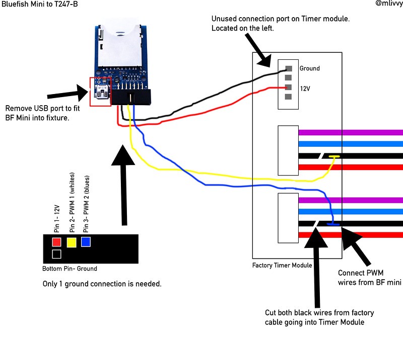
That's great! so if I connect pins 18 and 19 to the wires shown in the diagram below I should be able to control the with reef pi without anything else? Ignoring the blue fish mini controller.


Follow along with the video below to see how to install our site as a web app on your home screen.
Note: This feature may not be available in some browsers.



grounds should be connected as well.That's great! so if I connect pins 18 and 19 to the wires shown in the diagram below I should be able to control the with reef pi without anything else? Ignoring the blue fish mini controller.
To use the Pi's PWM pins, make sure pwm module is loaded in kernel: https://learn.adafruit.com/reef-pi-installation-and-configurationThat's great! so if I connect pins 18 and 19 to the wires shown in the diagram below I should be able to control the with reef pi without anything else? Ignoring the blue fish mini controller.


Kessil does not dim to 1%. The lowest I have been able to get is 10%. So, I configure reef-pi with a minimum threshold of 10% in the intensity channel. The spectrum channel (which controls the color) does go from 1-100%.Thats good to know! @Ranjib, are your lights on/off cycle 100% controlled by the PWM input? For example if pwm is at 0 volts the lights are off then 1% and up they turn on? Or do you have to control the power separate? Do you know the current draw for your PWM controllers?
I have two lights with 4 channels total, 2 white 2 blue. I would like to send the PWM signal to both white channels and both blue channels in parallel. You mentioned that the current capability of the pi is 20mA I thought I had read 50mA somewhere but regardless its probably to low to handle both lights so I was thinking to use a driver. I have found several mosfet drivers that use a 3.3 volt PWM input and use a higher current power source to drive the target but they are all 5 volts and up. I am still looking.
Kessil does not dim to 1%. The lowest I have been able to get is 10%. So, I configure reef-pi with a minimum threshold of 10% in the intensity channel. The spectrum channel (which controls the color) does go from 1-100%.
If you current draw is less than 50-70 ma , then a common NPN transistor (like 2n2222a) to pass the PWM signal before sending to lights, if its more than that (say 1 Amp) then go for power mosfet. Since you need four channels, you'll need a pca9685. Do you know by any chance whats the current draw is>


new kessil controller


Maker Faire's are the bestYou have made leaps and bounds over your first project! As everyone else has said thanks for all the effort you have put into this. It has really gotten me fired up. I even took my son to a Maker Faire a couple weeks ago.
. We have one (Bay Area Maker Faire) very close by to my apartment that we go everywhere. 5 years back when I first went there I was like... i want to be here, this is the community i want to belong to . And three years after that I was there as maker, exhibiting reef-pi builds. Its a great place for the kids. My son loves visiting there. I have couple of other projects (model railroad for example) that I am planning to exhibit next, may be after reef-pi development has settled a bit.


This weekend I upgraded my kessilncobtroller. I have built a new one during the adafruit guide development so this one is now replaced . I thought I’ll tear it down and salvage the parts I want (lm2596 modules , pi zero)....
Bye bye old kessil .
I have spend several days when this controller was not accessible via ui , due to network issues I suspect , but light cycle was spot on. I hated the fact that there was not way to power down the build other than unplugging the jack . All my follow up builds have spdt buttons now. I also didn’t like the cheap 3.5mm audio jacks (panel mount). These were so bad that they’ll almost always loose their grip if pressed hard. The gold plated ones are far far better, and only little bit expensive. Always go for those.
That's great! so if I connect pins 18 and 19 to the wires shown in the diagram below I should be able to control the with reef pi without anything else? Ignoring the blue fish mini controller.
My wife said the same for the first one. Which was even more strange lookingYou should keep that and one day use it for reef-pi museum. It is after all the original that started it all.
. I live in a small apartment so I just don’t want to hoard these .
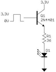
Dimming 40% with rpi driver? Did you try playing with the pwm frequency ? For me that helped dialing down the coralife moon light , which is powered by 12v 1amp signalSo i will not be doing this just because dimming 40% where my lights run to 10% is not really worth the effort. Maybe someday I will look into building my own LED's but for now the built in timer is fine. But if you decide to do this, and someone correct me if I am wrong I would not advise running it directly off the GPIO pin. I would use the following:
The PWM GPIO signal out would go in the 3.3v side with a square wave. Use the buck converter you linked above dialed down to 3.3.volts to supply the upper pictured voltage. D1 would be the OR light controller or where the black wire would connect. The key is to find out what the current draw is so that you can size the transistor and resistor appropriately. If you use the built in OR timers all you need to do is hijack the black wire and run ground from your pi build spliced into the red ground wire of the OR fixture.
If your your lights are anything like mine the clock sucks and never keeps time perfectly. So if you wanted to use the built in timers your brightness level and timer will over time be mismatched. To fix this disconnect the plug on the light. The purple and blue would need to be on a 12 volt relay timer programmed to come on and off at your set times with reef pi. The black wire would go to the same input on the transistor above and the red wire would go to your common ground. Since your clock is the same on both power and dimming you would be matched. Here is more on the OR light using the same basic concept.
Dimming 40% with rpi driver? Did you try playing with the pwm frequency ? For me that helped dialing down the coralife moon light , which is powered by 12v 1amp signal
Got it.I meant that I run my lights at 60% blue and 40% white during the day and turning them down to 10% they are still pretty bright. All the work and wiring is not worth it to me to dim them from 40% to 10% and 60% to 10% and then shut them off with a relay. Now if they dimmed from 40% down to 0% or 1% it would be worth the effort. But the OR light will not dim below 10%.


that reverse thing happens due to the use of N channel tansistors. In reef-pi UI you can configure each channel as "Active High" or "Active Low", to deal with this exact issueThis must have to do with the drivers. I had a Reef Radiance 240 or something. it was 30" long and had 6 total drivers (2 on each channel). the darn thing used a reverse PWM signal. Meaning 100% PWM was zero light and 0% was 100% brightness. I bought an analog to PWM board for the Archon controller I was using and the guy that made it changed the code for me to run in reverse of the 0-10V analog signal. they worked wonderfully.

This is a very good question, let me answer it in two parts:I have a question now that I am playing with the software. Why are things based on check intervals vs just on and off? For instance. If the ATO is set to check every 60 seconds and the switch is activated, it runs for a full minute even if the switch is no longer activated. Why not set it to turn on when the switch is activated and stop when the switch is off? I am sure there is a smart answer. Was just curios.
Second question. I have a pump on each side of my tank. Currently one pump is on for one hour then shuts off, the other pump then kicks on for an hour then shuts off and back and forth flip flopping. Is there a way to do this in reef-pi?











