OP
OP


- Joined
- Apr 16, 2016
- Messages
- 9,848
- Reaction score
- 17,081
- Location
- Pleasant Hill, Concord
- What state or country do you live in
- California
...Meanwhile...


Follow along with the video below to see how to install our site as a web app on your home screen.
Note: This feature may not be available in some browsers.



Looks great!...Meanwhile...
I'll do that when I get back home. Can I save a copy of the reef-pi.db and then restore it if i can corrupt it again? I think I may have had 4 rows because I have 3 temp sensors and wanted to see the equipment graph as well.Sorry for your trouble :-(
I tried to reproduce this without any luck. I have tried different combinations, including two columns, 1 columns, 2 row , 1 row, different width , height etc.
This is unlikely to do with Pi.. I am fairly sure theres a software bug in the UI code, thats running in the browser which is exposed when you make those changes. I also think this does not impact the controller itself (i.e. ato, lighting etc should work fine), it only breaks the UI. I'll keep trying to reproduce it. Fixing this type of bugs is trivial as long as we can reproduce it.
If its possible, just share the screenshot of the config that breaks the UI, without actually saving it, so that it does not break your UI. I completely understand if its too much ask.
Looks great!
I'll do that when I get back home. Can I save a copy of the reef-pi.db and then restore it if i can corrupt it again? I think I may have had 4 rows because I have 3 temp sensors and wanted to see the equipment graph as well.


Can you share your ato configuration(screenshot showing inlet , pump etc)? Does your ato setup work on test environment , like if you test it with a cup of water , dip the probe and take it off, does it work as expected ?
The dashboard send to be working fine, I can monitor 3 temp probes, equipment on/off cycles and memory/proc. If I recall, I set up the lights and thermometers and then it failed, then reset database and tried again before entering anything and it failed again.Before you set the Dashboard to the colums and Rows that Crash it. Do you completely set up the Hardware and Verify its all working before assigning dashboard charts. Or does it Crash before you can even assign dashboard Items?
In an older version I had a similar but with temp prob.The issue for me was the a bad Resister on the temp and it was not reading correctly. I found this by not adding the probs to dashboard and watched them in the Temperature tab and realized one was Broke.
Or does it freak out before you even assign a graph ?
Though we have not been able to reproduce this exact issue (and we'll continue to investigate this further), we are going to put some safety checks to ensure that just dashboard error (even if it occurs) does not crash the whole app: https://github.com/reef-pi/reef-pi/issues/627The dashboard send to be working fine, I can monitor 3 temp probes, equipment on/off cycles and memory/proc. If I recall, I set up the lights and thermometers and then it failed, then reset database and tried again before entering anything and it failed again.

Yes i have extended several temp probes up 20 feet . I use Telephone Cat3 cableHello, my temp probe came with 1 meter wire but its too short to reach the sump. Has anybody tried soldering an extra meter or 2 to it? Will this affect its reading?
@Erica-Renee That sounds cool. Do you just solder it on the wire?Yes i have extended several temp probes up 20 feet . I use Telephone Cat3 cable
Yes. I have successfully added 2m of wire to mine.Hello, my temp probe came with 1 meter wire but its too short to reach the sump. Has anybody tried soldering an extra meter or 2 to it? Will this affect its reading?

Did I read somewhere that Reef-Pi doesn't use SPIO (SP10??) and that you can disable it and use the pins (GPIO 8,7) for Relays?
I can't find where i read that.
Its in the first adafruit guide in install and config.
https://learn.adafruit.com/reef-pi-installation-and-configuration/raspberry-pi-configuration
Kewl.Well, so far my reefpi has been running on the bench with all my rules in place for several days now with no issue. I think I am done with the testing portion or power, temp, and ATO and ready to move to the next phase which is doser control. I know that the easiest thing to do would be to get a pi Zero and build it separate but I am suborn and determined to build it all together. I decided to go with the SPT SP200VO pump which has a max current draw of 150mA at 12 volts.
http://www.aptinstruments.com/Merchant2/merchant.mvc?Screen=PROD&Product_Code=SP200VO
I did a ton of reading on the subject and found that MOSFET motor drivers are preferred not only for the increased current capability but they tend to play nicer with micro controllers and dont cause resets from power spikes. With that said the dual channel TB6612FNG while its overkill for my project is used in lots of robotics projects, is good for up to 1.2 amp continuous per channel, and has flyback diodes built in.
https://learn.adafruit.com/adafruit-tb6612-h-bridge-dc-stepper-motor-driver-breakout/overview
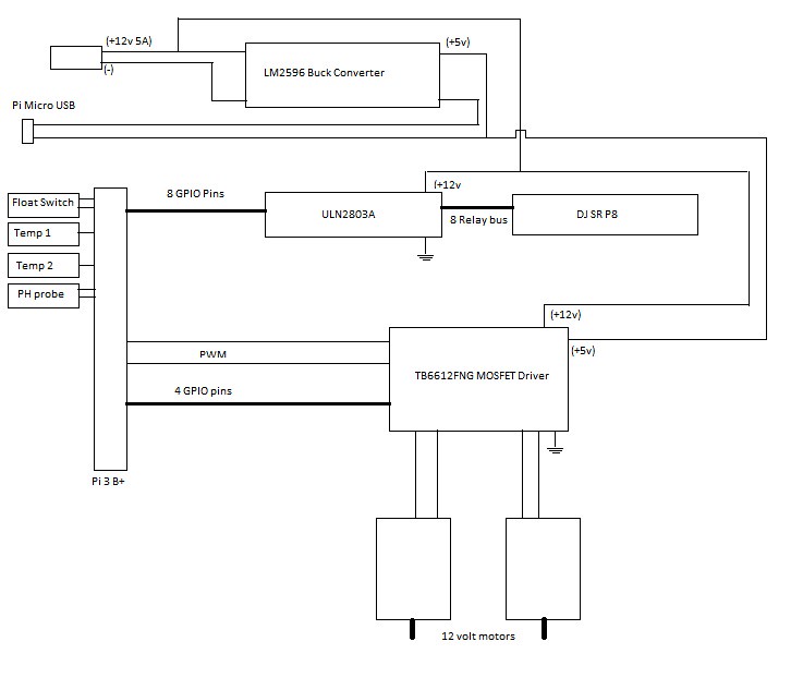
I am going to change things around a little on my pi, mainly I want the built in circuit protection so I will be wiring it up to get power from the micro USB port connected to the buck converter. I will also be upgrading my power supply to a regulated 12v 5 amp power supply. For those that are electronics smart. The only question I cant seem to find a definitive answer on is will I need decoupling capacitors on the LM2596 regulator be sufficient for keeping spikes or noise down? I know the pi itself has some built in. Here is a basic diagram.

Well, so far my reefpi has been running on the bench with all my rules in place for several days now with no issue. I think I am done with the testing portion or power, temp, and ATO and ready to move to the next phase which is doser control. I know that the easiest thing to do would be to get a pi Zero and build it separate but I am suborn and determined to build it all together. I decided to go with the SPT SP200VO pump which has a max current draw of 150mA at 12 volts.
http://www.aptinstruments.com/Merchant2/merchant.mvc?Screen=PROD&Product_Code=SP200VO
I did a ton of reading on the subject and found that MOSFET motor drivers are preferred not only for the increased current capability but they tend to play nicer with micro controllers and dont cause resets from power spikes. With that said the dual channel TB6612FNG while its overkill for my project is used in lots of robotics projects, is good for up to 1.2 amp continuous per channel, and has flyback diodes built in.
https://learn.adafruit.com/adafruit-tb6612-h-bridge-dc-stepper-motor-driver-breakout/overview
I am going to change things around a little on my pi, mainly I want the built in circuit protection so I will be wiring it up to get power from the micro USB port connected to the buck converter. I will also be upgrading my power supply to a regulated 12v 5 amp power supply. For those that are electronics smart. The only question I cant seem to find a definitive answer on is will I need decoupling capacitors on the LM2596 regulator be sufficient for keeping spikes or noise down? I know the pi itself has some built in. Here is a basic diagram.
LM2596 modules are rated for 3A, if I recall correctly. I think the motor driver is nice choice. I have not used them, most of my needs are met by l293d already. I am assuming like l293d these chips also has some fly back/diode protection.
One thing to consider is you can house the dosing pumps in a seperate enclosure and just connect the pwm signal from reef-pi brain to the dosing enclosure using audio cable (for two channels), or cat5 cables (for 10 channels). When I thought about an all in one controller including doser, I found it rather inconvenient to have the brain and dosing pumps together, cause dosing pump might be located in a very different location (close to sump or back chambers for AIO tanks) than brain.

I am busy with the designing of what I am calling "Reef-Pi Reboot"
At present, my Reef-Pi is built into an old PC Tower case that I had kicking around. The original idea was to use the ATX power supply, but that died half way through the build. - Probably the reason the case wasn't being used in the first place. This hasn't worked out so well because I found that that because of where the Reeftank is placed, WiFi is quite weak there and the Pi got terrible WiFi signal through the metal case. So now it lies there on it's side with one of the covers off and looks rubbish. I've also lost a few channels on the 8-channel relay bank. My ATO problems also point to a hardware issue, so a total rebuild can't hurt. I have also been given a Pi 7" screen that I want to mount on the case ie right there next to the tank. Will be great for turning equipment on or off if needed without digging out a phone or something.
My challenge is how to make the wiring look neat and how to hide all the wires that run from the "brainbox" to all the equipment. The wires I'm talking about are quite a number. I know guys use DB9 cables and cat5 cabling to neaten some of this up and reduce the number of actual cables involved. Ultimately I think that a run of trunking is going to be the way to go. Also, the "stereo jack" system of connecting up. I've never like the look f that or the work involved. I'm thinking about using these instead for all the equipment https://www.bidorbuy.co.za/item/374176156/Jack_Spring_4_Wire_Speaker_Terminal.html If correctly labeled, I can see no real cause for confusion.
Any other ideas / thoughts on this subject?

@b4tn - have you considered a banana plug wall plate? Here's a sample of one but they're available in a number of styles.I have not had the best of luck with the stereo connectors. They are very finicky. I want to switch to a different type of plug but have not found anything that I really like yet. I like the idea of using telephone or cat 5 cable but have not really found any panel mount female ends that are not bulky and require a crimper tool. DB9 plugs are easy if you dont mind everything bundled into one cable but I kind of want individual cables per component. If you find anything good make sure and post it up.










