

reef-pi :: An opensource reef tank controller based on Raspberry Pi.

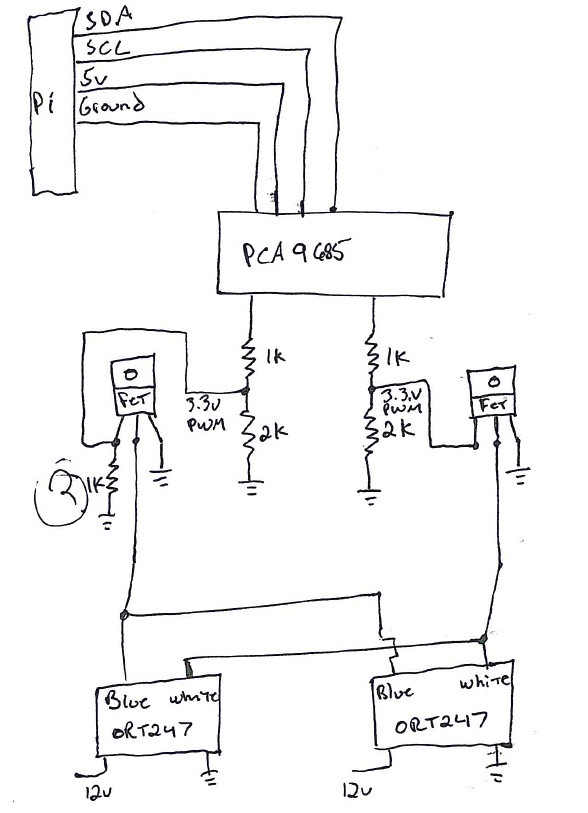
Can I get some input from any of the electronics gurus in here. @Diamond1 has convinced me to add my lights to reef-pi. I have two Ocean Revive T247 lights and he has confirmed that they run off 0-3.3v PWM at 1khz. Since all my blue and whites are the same I was thinking to just run the 2 ORT247 PWM inputs in parallel and use FETS or a 2N2222A to isolate the output pins. in the crude diagram below I have two resistors forming a voltage divider to step the voltage down to 3.3v. I am not sure why the gate of the FET goes to ground through a 1k resistor but I have seen it in other diagrams. (maybe someone can tell me why its there)? Does anyone see any reason this would not work?
46092610841_1aa75e8290_b.jpg
 
Last edited:
Can I get some input from any of the electronics gurus in here. @Diamond1 has convinced me to add my lights to reef-pi. I have two Ocean Revive T247 lights and he has confirmed that they run off 0-3.3v PWM at 1khz. Since all my blue and whites are the same I was thinking to just run the 2 ORT247 PWM inputs in parallel and use FETS or a 2N2222A to isolate the output pins. in the crude diagram below I have two resistors forming a voltage divider to step the voltage down to 3.3v. I am not sure why the gate of the FET goes to ground through a 1k resistor but I have seen it in other diagrams. (maybe someone can tell me why its there)? Does anyone see any reason this would not work?

46092610841_1aa75e8290_b.jpg
Any reason you would not just run it from the two PWM channels on the pi?
Also, if you do stay with the PCA9685, you can run it off of 3.3V from the pi, then no reason for voltage dividers or the FETs, just wired straight to the pca9685 PWM outputs.
 
Any reason you would not just run it from the two PWM channels on the pi?
Also, if you do stay with the PCA9685, you can run it off of 3.3V from the pi, then no reason for voltage dividers or the FETs, just wired straight to the pca9685 PWM outputs.

I am already using the built in PWM pins. Thanks for the input, I didnt realize that the PCA9685 could be run off 3.3 volts. Would there not be a need to isolate the outputs? I am not sure what the current draw is from the OR lights.
 
I am already using the built in PWM pins. Thanks for the input, I didnt realize that the PCA9685 could be run off 3.3 volts. Would there not be a need to isolate the outputs? I am not sure what the current draw is from the OR lights.
THE 3.3V Is the pwm signal not the Power for the lights. you still need to isolate the Higher Voltage of the lights from the lower voltage pwm. this is where the mosfits come in play at..
 
THE 3.3V Is the pwm signal not the Power for the lights. you still need to isolate the Higher Voltage of the lights from the lower voltage pwm. this is where the mosfits come in play at..

I did 4 years of high school electronics but that was 25 years ago lol. Maybe my terminology is off. The lights have their own 12 volt power source so I just need to make sure the lights and pi have a common ground. My concern is that the outputs on the pi and or the PCS9685 or only capable of suppliying if I read correctly max 50mA. Even the the pwm wire is low voltage I am sure it still has a current requirement but I’m not sure what that is. I know @Diamond1 ran a single light straight of the pin and it was fine but if I add 1, 2, 3, or 4 more? That’s what I was thinking the transistor or FET was there for. So the pwm signal can use a transistor to control a higher load. Kind of like a relay.
 
I did 4 years of high school electronics but that was 25 years ago lol. Maybe my terminology is off. The lights have their own 12 volt power source so I just need to make sure the lights and pi have a common ground. My concern is that the outputs on the pi and or the PCS9685 or only capable of suppliying if I read correctly max 50mA. Even the the pwm wire is low voltage I am sure it still has a current requirement but I’m not sure what that is. I know @Diamond1 ran a single light straight of the pin and it was fine but if I add 1, 2, 3, or 4 more? That’s what I was thinking the transistor or FET was there for. So the pwm signal can use a transistor to control a higher load. Kind of like a relay.
I think it's there to boost the voltage on the pwm pin so you can use 0-10v pwm, without added components the output is just 3.3v from the pwm so that's why it's boosted to 10v, I'm thinking you will need to get 0-5v from the pwm pin with suitable transistor and maybe resitor.
My understanding is you will need to do each pwm output the same for each channel.
 
I did 4 years of high school electronics but that was 25 years ago lol. Maybe my terminology is off. The lights have their own 12 volt power source so I just need to make sure the lights and pi have a common ground. My concern is that the outputs on the pi and or the PCS9685 or only capable of suppliying if I read correctly max 50mA. Even the the pwm wire is low voltage I am sure it still has a current requirement but I’m not sure what that is. I know @Diamond1 ran a single light straight of the pin and it was fine but if I add 1, 2, 3, or 4 more? That’s what I was thinking the transistor or FET was there for. So the pwm signal can use a transistor to control a higher load. Kind of like a relay.

I still have the my light fixtures apart and tested it to see if 1 gpio could control both channels at the same time and it worked without any issues. I don't see why you would need anything other than the 2 pwm signals straight from the pi and couple relays to run both fixtures.
 
I still have the my light fixtures apart and tested it to see if 1 gpio could control both channels at the same time and it worked without any issues. I don't see why you would need anything other than the 2 pwm signals straight from the pi and couple relays to run both fixtures.
. Awesome. I’m going to start piecing together parts.
 
Any reason you would not just run it from the two PWM channels on the pi?
Also, if you do stay with the PCA9685, you can run it off of 3.3V from the pi, then no reason for voltage dividers or the FETs, just wired straight to the pca9685 PWM outputs.

There is no reason to voltage divide for the FETs in either case - even logic level FETs perform correctly at 5V, and non-logic-level FETs won't even switch on at 3.3V.

If anything, you want a small series resistor (say, 10 ohms) in series with the FET gate.
 
I did 4 years of high school electronics but that was 25 years ago lol. Maybe my terminology is off. The lights have their own 12 volt power source so I just need to make sure the lights and pi have a common ground. My concern is that the outputs on the pi and or the PCS9685 or only capable of suppliying if I read correctly max 50mA. Even the the pwm wire is low voltage I am sure it still has a current requirement but I’m not sure what that is. I know @Diamond1 ran a single light straight of the pin and it was fine but if I add 1, 2, 3, or 4 more? That’s what I was thinking the transistor or FET was there for. So the pwm signal can use a transistor to control a higher load. Kind of like a relay.

It all depends on the input of the dimmer circuit. Many things will just be logic gates or FET gates, so the overall current requirements are moot (small high current pulses at the transitions, zero in between). If anything, on long wires, you can end up with ringing so adding a series resistor is good form (and you'll not turn your wiring harness into a radio transmitter as badly).
 
There is no reason to voltage divide for the FETs in either case - even logic level FETs perform correctly at 5V, and non-logic-level FETs won't even switch on at 3.3V.

If anything, you want a small series resistor (say, 10 ohms) in series with the FET gate.
Exactly . I think this is what I have put in the light guide as well.
You need mosfets only if you are controlling more than 500ma . For less than 150ma a common npn transistor will do. It’s a good idea to put resistor in series for safety .
 
It all depends on the input of the dimmer circuit. Many things will just be logic gates or FET gates, so the overall current requirements are moot (small high current pulses at the transitions, zero in between). If anything, on long wires, you can end up with ringing so adding a series resistor is good form (and you'll not turn your wiring harness into a radio transmitter as badly).
On this topic, @theatrus , when one should go for mosfet vs a full blown meanwell driver? Or the builder has to know if the light requires constant current/voltage ?
 
On this topic, @theatrus , when one should go for mosfet vs a full blown meanwell driver? Or the builder has to know if the light requires constant current/voltage ?

All LEDs should be driven by a constant current driver - if its a commercial/blackbox/etc fixture, it should already have a constant current driver.

If the driver has an dimmer input, this should be very low current, logic level PWM or 0-10v low current as a control signal only.

If the driver doesn't have a dimmer input, you can often chop the actual constant current driver output by effectively disconnecting the LED string cathode at the PWM dimmer frequency - this will require a FET as you're controlling the full string current directly. Some drivers don't like this and will shut down (thinking everything has gone open circuit, which may cause the output anode to go very high voltage) or not respond correctly, so this is usually a mechanism of last resort.

If you're building your own LED string, use a constant current driver (Meanwell, blueAcro ones, etc) that you can control. Most support logic level PWM.
 
So dosing controller is the last part, or are you looking at adding more feature in future?
Yes, for 2.0 release this was the last that I had planned for. I might publish a few other guides, to showcase macro, building a comprehensive dashboard using reef-pi or some other niche topic, camera etc ... but this is the basic controller features (1 install guide + 6 module specific guides) that I wanted to go out as part of 2.o release.
 
All LEDs should be driven by a constant current driver - if its a commercial/blackbox/etc fixture, it should already have a constant current driver.

If the driver has an dimmer input, this should be very low current, logic level PWM or 0-10v low current as a control signal only.

If the driver doesn't have a dimmer input, you can often chop the actual constant current driver output by effectively disconnecting the LED string cathode at the PWM dimmer frequency - this will require a FET as you're controlling the full string current directly. Some drivers don't like this and will shut down (thinking everything has gone open circuit, which may cause the output anode to go very high voltage) or not respond correctly, so this is usually a mechanism of last resort.

If you're building your own LED string, use a constant current driver (Meanwell, blueAcro ones, etc) that you can control. Most support logic level PWM.
I am thinking of LED strips from reefbrite, trulumen or coralife. I current use power level mosfets. Although most of these are used as moon light, so only a few moinutes at night as and when I want/ on demand
 

IF YOU HAD TO TAKE A REEFING EXAM, WOULD YOU PASS?

  • Yes!

    Votes: 32 45.7%
  • Not yet, but I have one that I want to buy in mind!

    Votes: 9 12.9%
  • No.

    Votes: 26 37.1%
  • Other (please explain).

    Votes: 3 4.3%
Back
Top















