Reef-Pi The All In One Pi Challenge

Since you had them as grounds do the LEDs light us I'm pretty sure they are 12v
Yes they light up, but don't put power directly to the LEDs, I burnt all mine out with my multimeter and had to replace all, it's been working for a couple of months.

The pumps require 12 volts.
 
I used these shields.
IMG_20190115_203832.jpg
 
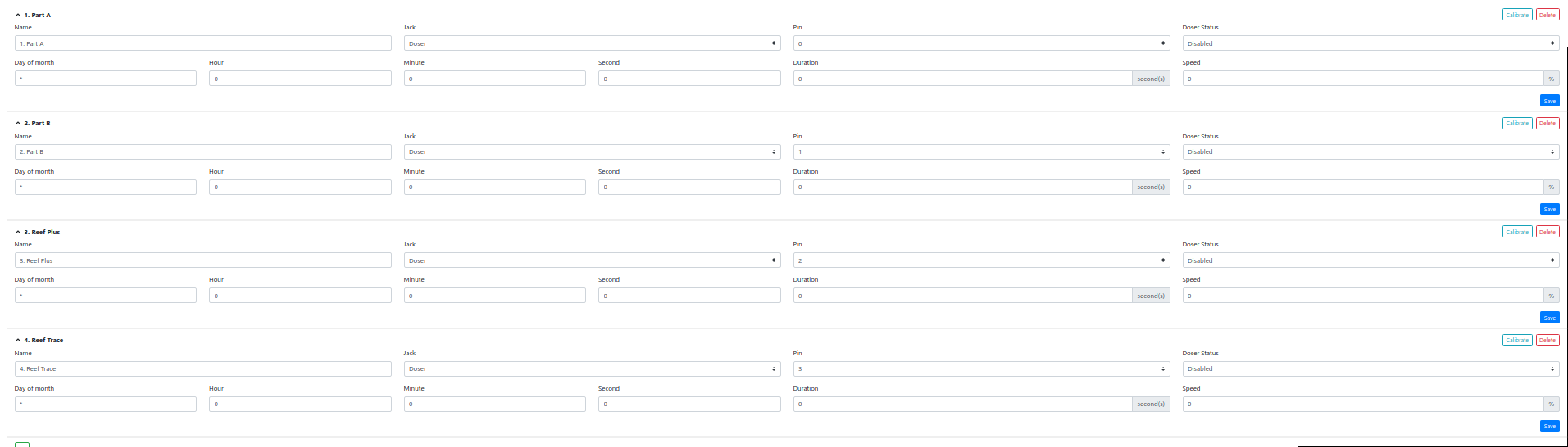
@Michael Lane @Ranjib I have everything soldered and setup ready to go. I am confused as to how to make the doser work on the web ui. I am confused as to what jacks and pins to declare to make this work. I have enabled the PCA9685 and doser.
f4aa4eb80708b1b905e7a1c043cf3220.png
jmazsP9aQM8nxKOcM_oecCmWRiF5drcqZ-rGRUp5N1nqgHopX-KKMHXiX4KREKWmxSmrrEKqMeo4i-KHtx74FkDXdDYPxuoei2ddAsJsZ5gK3-qJ0zdWWAHZQ8ALd97u-B2CQrcspuDhwEiqmf0drUYP_6r6Jvpi2x-XSIUbMDFD1Ly0b5FcGbK5l1UKwfu4NXNKltaOCOO39AMi09LnMMYWR8Sr-MdcG70s-iUckXfI1YqWBdwm4_cN7DV--gYNO-YHpdWvpZCFAvetUfqA0guMEKHhyunsxt_66QXvOZf-XRLw09as86qLaRaiynIMoiueMl94xzurPa1rSRVZQoJaTS2QWTQX7SYuFAnu1kBerI5a8zfhPuVRDqNIi2qrU90a399daSQuDt_dYbBux3ctFoRcdaqZdMEk4AZQE_HPMn2vEyM1119m5RPuQX5GhF2zdm7aoZaKsn3Zq5qC2h1PCAT8rDjAQvs_QK2PhcwZZuGwtLdxuZbT-8URavQdaPFNbdcTwtGMz3uB4Y4xB8SLy0jFjxY9ERD-j9hjYKw2ekGti146hysNQcUhq2rUWIbbcuaIrOUacGcgR5EDTaW5ypio_dRCr76C4YOa9V5TxCS9jnOH4_tcWXfiT5A1K9OlLs-56FzogaadhYrrWCLiiDm9r337=w669-h891-no
LWb9HwElsSTEt9S951pyB6EMz-zWD6U_uFV1ZzblBANTiAGXdGc9KHCsAwLnSiqq76rgPwLC4MR_oweBl39gO_mntxNBf3bNQhsJcZfSKYP_X3VixYZfK3k2TRx6orxLGKIyweAXIxQqNzZtshwa5-577Sd3TwLz8yCeX2UbkDWyHs4zsUjUXWD6ck1mkz7nJ67sMUdSUwWvT2pHfZZPzYb2u4yh8DqPxbnPpU9-hrQsI5X3hieMFroKE4GKzZaGKOcn8dX1CwZqxdXdUnDuf8jim2WXfZKfXipX7a78ERuUT_2fpzPfXn2qj_ZoiLIJIATPQ79CG8FHbIsZ_5Ud8kdBUv6qM-K8rgr-L0gRwg6HDUOX8j3Skij6ObFqZgjzvbpXVQH5VjPy1u_o2jpL3l3qFutVHc5OL1h60XRezrMVJiCR82Ks1ghFK8zXgu-9pfT-6Jsf-HnQGJx-kp428YZi0TCrqwLB7-tlXN6z81tDLnDLkE0oyry9qjg5z0AlKPe_qFHT_eR_7Cdgg5Ws_ujb6JfqbyrFcB6_znsyy_-4_rvjjMBvmEid2llo_Sjy8xSNKA2_XRS-AUG4thmqgd9tXLBAjBrz9cESEq3e_jBfBqdPMrNF35eX-NomYWWHMb3jdEdz0XrqMV_GWLEb0Qoqb3CjwNa2=w669-h891-no
You have soldered 4 pwm output, you can declare either 1 jack with 4 pins or 4 jacks each with one pin, whatever you like. Use pin number 0 , 1,2 and 3.
This does not matter technically, but its against convention to use black wire for pwm or similar outputs, since its common to represent GND. Once you have declared the jacks , say J0 with pin 0, you can then associate it with a doser
 
You have soldered 4 pwm output, you can declare either 1 jack with 4 pins or 4 jacks each with one pin, whatever you like. Use pin number 0 , 1,2 and 3.
This does not matter technically, but its against convention to use black wire for pwm or similar outputs, since its common to represent GND. Once you have declared the jacks , say J0 with pin 0, you can then associate it with a doser
Only a stupid butt Chinese doser would use those wires for signal lol.
 
You have soldered 4 pwm output, you can declare either 1 jack with 4 pins or 4 jacks each with one pin, whatever you like. Use pin number 0 , 1,2 and 3.
This does not matter technically, but its against convention to use black wire for pwm or similar outputs, since its common to represent GND. Once you have declared the jacks , say J0 with pin 0, you can then associate it with a doser
Ok so I have got that setup but it's not running a calibration. Nothing happens.
Do I need to create virtual equipment as per the guide?

c40a24a85c4613fd8963a89ac040834e.png

cbc6967d326a02bbe3a0e7cde4d2ac47.png
 
is the ULN2803A Directional as I have the in signal wires as the same side as the 12v instead of the ground as how the diagram shows with the signal in wires on the grounded side
 
I noticed a bug in the doser calibration when I was setting up my doser. The calibration didn't run for the duration and speed that I set; instead, it was running the duration and speed set in the doser configuration. Try setting the speed and duration, then clicking through calibrate.
I'm not sure if that's been fixed in a subsequent release.

Is the red wire from the V+ rail on the proto board at 12v?
I don't see another wire going from the proto board to the doser to provide 12v to the doser. Is that wired in somewhere else?
 
I noticed a bug in the doser calibration when I was setting up my doser. The calibration didn't run for the duration and speed that I set; instead, it was running the duration and speed set in the doser configuration. Try setting the speed and duration, then clicking through calibrate.
I'm not sure if that's been fixed in a subsequent release.

Is the red wire from the V+ rail on the proto board at 12v?
I don't see another wire going from the proto board to the doser to provide 12v to the doser. Is that wired in somewhere else?
It is at 12v I have the two wires grounded now as the 12/v didn't work . I will try your trick.
 
I noticed a bug in the doser calibration when I was setting up my doser. The calibration didn't run for the duration and speed that I set; instead, it was running the duration and speed set in the doser configuration. Try setting the speed and duration, then clicking through calibrate.
I'm not sure if that's been fixed in a subsequent release.

Is the red wire from the V+ rail on the proto board at 12v?
I don't see another wire going from the proto board to the doser to provide 12v to the doser. Is that wired in somewhere else?
Tried with both wires grounded and both at 12v. I set the speed and duration and still nothing. How can I troubleshoot?
 
You need to tie all the grounds, on your PCA 9685 output your ground isn't even connected to anything.
 
Ok, so if your grounds are all tied and checked for continuity, one thing that might be your issue is that according to @Ranjib 's circuit you can only control 2 motors per l293d Ic, although the IC itself can do 4 it may not put out enough current to turn the motor. I'm using a pair of l293d's for my dp4s, the motors won't spin reliably under 50% PWM.
 
Ok, so if your grounds are all tied and checked for continuity, one thing that might be your issue is that according to @Ranjib 's circuit you can only control 2 motors per l293d Ic, although the IC itself can do 4 it may not put out enough current to turn the motor. I'm using a pair of l293d's for my dp4s, the motors won't spin reliably under 50% PWM.
I don't have any l293d as that wasn't part of @Michael Lane s wire diagram
 

IF YOU HAD TO TAKE A REEFING EXAM, WOULD YOU PASS?

  • Yes!

    Votes: 32 45.7%
  • Not yet, but I have one that I want to buy in mind!

    Votes: 9 12.9%
  • No.

    Votes: 26 37.1%
  • Other (please explain).

    Votes: 3 4.3%
Back
Top